Detail S-1387 Machine Tool Geometry Software
S-1387 Machine Tool Geometry Software
Description:
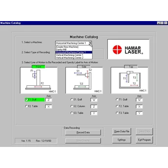
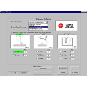
The Machine Tool Geometry Software is a Windows-based program for machining center alignment. It is used with our continuously rotating laser systems ( L-743, L-742, L-741, L-733, L-732, L-731, L-723, L-722, L-720 and L-720M) to measure and analyze the lines of motion of the machine' s main axes. Geometric errors, such as flatness, squareness, straightness and parallelism, are automatically downloaded using the our wireless IR receiver ( A-908) or our computer interface ( R-355) . The MACHINE CATALOG page shows front, side and top views of the machine tool, and displays all the lines of motion for each view. The label of the machine' s main axes can be customized to the individual machine type ( i.e., X axis, Y axis and Z axis) . It also allows the user to choose a machine configuration from 5 different types of machine tools and automatically updates the computer graphics to display the chosen machine type. It even lets those with AutoCAD skills to design their own machine graphics. Straightness tolerances for each line of motion and squareness and parallelism between them are chosen on the MACHINE CATALOG page, as well. The SETUP page is where the user chooses the length, number of points and distance between the points for each line of motion. The type of target, target orientation, direction of measurements, alignment tolerances and interface to be used in the measurement are also chosen here. The DATA TAKING page displays the measurement in a readout box and updates the graph of data as it is recorded. After each point is recorded, the cursor automatically moves to the next point and the least-squares, best-fit line is calculated. Multiple measurement " runs" and bi-directional data can also be recorded for each line of motion. The VIEW PLOT screen shows a graph of each line of motion for a given view ( such as top view) . Many viewing choices are available, such as: tolerance bands, TIR with high and low points, and squareness and parallelism angles ( slope of best-fit line) between axes. Any line of motion can also be chosen as the datum and the other axes are re-plotted to reflect the new reference. The angles and graphs can be zoomed in or out, and a forward-run average, backward-run average or an overall average can also be graphed. The VIEW PLOT screen can also compare a previous set of data to the newly recorded set. Click a button on the bottom of the page and the data behind the graphs are displayed along with their compliance to user-defined tolerances.
Features:
• Multiple machine graphics for customized data taking and display. Can add your own AutoCad-generated graphics as well.
• Records and analyzes flatness, straightness, squareness and parallelism misalignment data for each line of motion using one program.
• Real-time graphs show data as it is recorded for each line of motion.
• Can customize axis labels ( i.e., W, X, Y, Z, etc.) for individual machine types.
• The user can save and print recorded data, as well as recall previously saved machine data for comparison to existing alignment conditions.
• User-definable tolerances for each line of motion and squareness and parallelism between axes.
• Alignment graphs simultaneously show up to 4 lines of motion for straightness/ flatness, squareness and parallelism.
• Graphs show TIR, high and low points, tolerance bands, squareness and parallelism errors in inches/ ft. User can zoom in on straightness, squareness and parallelism graphs as well as choose one line of motion as the datum. User can choose between the " forward" lines of motion and " backward" lines of motion.
• Reports print the analysis graphs as well as all backup data.
• Also supports manual data entry.
Laser digital indicator, Digital Dial indicator, Alignment laser, shaft alignment system, spindle alignment system, bore alignment system, geometric alignment, kerataan sumbu saat instalasi mesin, kesejajaran, kerataan jasa alignment lubang, alignment shaft, Roll Aignment, Power Generation, Auto Industry, Fabrication, Machine Tools, Aerospace, Plastic Processing, Plastic Products, Geomatric Alignment.
Distributor agent penjualan training service repair, upgrade dan perbaikan
Jakarta - Indonesia
TELP. 8611444 ( hunting)
Call : 0815 614 1954, 0813 992 919 09, 0811 893 101
Tampilkan Lebih Banyak